Speaker Placement and Acoustic Environment Effects
on Nearfield Monitor Systems –
MIX Magazine
To Woof Or Not To Woof? A SUBstantial Question – MIX Magazine
Optimizing the Studio Listening Environment – MIX Magazine
Acoustic Solutions, The RPG B.A.S.S. Trap – MIX Magazine
Examining the Yamaha NS-10M “Tissue Paper Phenomenon” – Recording Engineer/Producer Magazine
Educational Resources
Articles written either for MIX
Magazine or Recording Engineer/
Producer Magazine.
– by Bob Hodas
Gain insights into studio listening environments and rooms.
Optimizing the Studio Listening Environment
MIX Magazine, October 1995 – by Bob Hodas
As an engineer and consultant, I have had the opportunity to work in a wide variety of control rooms around the world. In my experience, every control room is unique. Of course, some monitor types are more popular than others, but no single soffitted speaker design dominates the market. Similarly, room sizes, wall treatments and reverb times all vary. But one thing common to 95% of the rooms I have seen is that equalizers are in use for "tuning" the speakers to the room. Purists may argue that a properly designed control room and speaker system interface does not require equalization. Without getting drawn into that argument, I submit that there is general agreement that an acoustic solution to a room problem is preferable to an EQ-only solution. However, if acoustic solutions are impractical or fail to cure a room's problems, then equalizers are called for. Equalizer technology has come a long way since early designs (which often introduced massive phase shift), and complaints about room EQ sounding "electronic" are rarely heard today.
The "Flat Response" Myth
Many audio professionals assume, not unreasonably, that the whole purpose of room tuning, whether acoustically or through EQ, is to make the room "flat". In fact, I have het to find an engineer or studio owner who actually wanted a "flat" room. Experience shows that a flat room has no personality and is no fun to work in. Equally important, working in a flat room does not necessarily ensure a recording that sounds good elsewhere.
In general, most rooms conform to what is known as the "analog curve" - a gentle, linear roll-off starting in the upper midrange. Two factors in particular have contributed to the development, or evolution, of this curve. The first factor is the progressive high-frequency loss characteristic of analog tape - high frequencies are gradually erased throughout the overdub and mixing processes as the tape passes over the machine heads again and again. High frequencies are also lost as the magnetic particles on the tape realign themselves to their "at rest" positions. The roll-off adjustment in the speaker system - the analog curve - allows the engineer to compensate for HF loss by putting a brighter sound on the tape initially. Then through the recording process, the extra high end eventually finds the middle ground.
The second factor stems from the human ear's reaction to extended periods of high-volume listening. A slight top-end roll-off can have the effect of reducing high-frequency listening fatigue, helping avoid the problem of mixes ending up too bright.
Many digital room owners want the high end fairly flat, as there is no high-frequency loss (roll-off below 20 kHz) in the digital domain. However, the fatigue factor is still at work, and if any roll-off is applied, it is usually based on the engineers listening levels. I believe that one of the reasons many of the early digital recordings were harsh is that they were made in rooms originally set up to do analog work. Old habits die hard in the audio trade.
Low End Bumps Add to the "Fun Factor"
Regarding the low-frequency curve, most people prefer a slight bump in the bottom end. This gives the impression of a larger space, which is associated with a longer reverb time. Most concert halls exhibit this sort of low bump. It seems to equate with the "fun factor" in the room. This curve seems to vary from studio to studio based on the engineers preference and the music style, but care must be taken not to exaggerate the bump, as recordings may turn out bass-shy. I have only tuned one room where the engineer wanted the bottom flat.
Between the high/low personality filter, the best results throughout the midrange are achieved with a linear, or flat tuning. Looking at rooms with 1/48th octave resolution, a straight line is impossible to achieve, and this stems from a number of factors. First, there are console reflections. I have seen a few well-designed rooms where soffitted speakers interact at a minimum with properly raked console topology, but in most cases, path length differences between the speaker/listener path and speaker/console/listener path create cancellations at the mixing position, causing holes in the frequency response.
Near-field speakers can also cause console reflection problems. Simply moving the near-fields back a foot or so can minimize this interaction (see November 1994 Mix). Reflections from the ceiling and/or walls that bounce back into the mix position with the Haas window (within 18 ms of the direct signal) are also destructive. These undesirable boundary reflections can often be acoustically treated and minimized in a cost-effective manner for the mid-to-high frequencies, but are more problematic on the low side. If not properly angled, equipment racks can bounce first-order reflections to the mix position. Additionally, scurrilous room modes wreak havoc on many rooms low-end response.
Even small, closely placed monitors are affected by room modes and acoustic problems. I am not recommending that everyone equalize close reference systems, but if a small monitor is your only system, you are probably working in a small room, so some acoustical treatments and, most likely, an equalizer will help. Most important is assembling a creative listening environment that translates to the outside world. If you are finding that more than a dB of EQ is being applied to your mixes in the mastering room, then you need to "tune up" your studio.
New Components May Affect System Linearity
Although most studios understand the need to "tune up," there is quite a bit of confusion about maintaining the system tuning. First, any changes in the physical arrangement of the listening environment will have some effect on the acoustics. For example, if you have changed or added wall treatments or traps, then you have also changed the linearity of the system response and the room's reverb structure. Similarly, the addition of an equipment rack will affect the room's volume and mass, and may effectively change wall angles. If you change consoles, then you have probably changed the angle of the work surface, and because most console upgrades mean additional inputs, the console's mass in the room may be larger. Changing from a console that is closed in front to the floor to one that has an open front can make a huge difference in the way the bass rolls through the room. I have seen major changes in linearity as a result of moving the tape machines from the back of the room to a position beneath the speaker soffitt.
Changing electronic components can also make a big difference in linearity. New amplifiers may handle your speaker impedance or wire capacitance differently and cause changes in linearity. I have witnessed changes of several dB in different parts of the spectrum when clients switched between solid-state and tube amps. Of course, changing the crossover point itself will also have an effect on the system.
Check the system response whenever you change a speaker component. I have seen fluctuation by as much as 3 dB across the range of a speaker when an old element was replaced with a new one. Sensitivities will vary, and many manufacturers do not have a tight grip on quality control. As with any equipment changes, it is important to maintain overall system polarity.
Good Coffee is No Substitute for Maintenance
You should schedule regular system tuning even if you do not change equipment. As speakers age, their resonant frequencies change and the room/speaker tuning will "drift" out. How long that takes depends on how often and how loud a system is driven. A few studios tune their system every three to four months. If a really loud alternative or rap group is in your studio for three or four weeks, you can probably count on some damage being done. A moderately driven system can often go six months before changes in linearity occur. Some facilties (often media or post) who work at modest volumes can often go a year before needing attention.
Sadly, the typical response to a proposed regular maintenance tuning schedule is "I can't afford that." So, how important is sound in our business anyway? Most studios spend more money of coffee than on control room monitor maintenance. Even sadder is the following typical scenario: A studio that has its room tuned but does not follow a maintenance schedule. At some point after the room really needs another tuning, a producer listens to the studio for an upcoming project. Unhappy with the sound, he takes the project elsewhere. If the studio owner had been more concerned about the way the studio sounded, this would not have happened. Ironically, sound takes a back seat to gear in many studios. For most engineers, the latest toys seem to be more important when booking a studio than how good the room sounds.
A Third-Octave EQ is No Match for Parametrics
Conversations with studio owners and engineers reveal that there is little awareness of the difference among the types of equalizers commonly used for treating speaker/room interface problems. In my experience, 90% of the equalizers used for tuning control rooms are 1/3-octave models. These equalizers were originally designed as shapers for the NAB and RIAA curves. They later gained popularity for sound shaping and were then applied to room tuning. However, room acoustics are anything but well-behaved phenomena. Resonant frequencies rarely coincide with the center frequencies of a 1/3-octave graphic EQ and almost never exhibit the same fixed Q. As a result, one often winds up equalizing more than necessary or can't get to the problem at all using 1/3-octave EQ. In my book, 1/3-octave EQ is now "old school."
Enlarge view
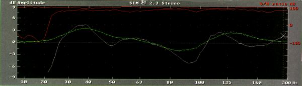
Figure 1: 1/3-octave EQ attempt to correct low-end problem (inverse of EQ shown). White trace is frequency response; green trace is EQ inversed.
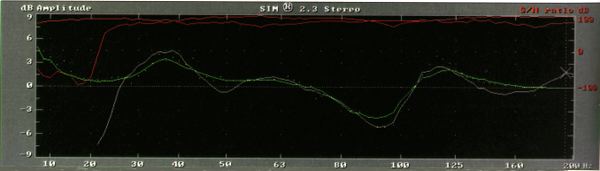
A parametric equalizer, on the other hand, allows the user to dial in the exact center frequency and bandwidth curve necessary to address the problem. Figs. 1 and 2 demonstrate the point. (Note that the EQ curve is an inverse of the EQ that is being applied. This simply makes it easy to see how it fits into the room curve.) Fig. 1 shows the low end of a room curve with a 1/3-octave solution applied to it. Notice that you can't quite get to the problem and wind up affecting more frequencies than necessary, especially around 150 Hz. Fig. 2 is the same room with a parametric solution. The parametric allows a much better match.
Enlarge view
Figure 2: Parametric EQ correction of low-end problem (inverse of EQ shown). White trace is frequency response; green trace is EQ inversed.
In the past, parmetrics were notorious for introducing extraordinary phase shift. Today, many units have this problem solved, and some room equalizers of modern design even use minimum phase filters. Minimum phase filters allow for more latitude to boost or cut without hearing excess phase shift. I would like to see more parametric manufacturers use second order filters in their high/low pass filter sections. Second-order filters are much more applicable to room tuning than third- and fourth- order filters, which are designed mainly for noise removal.
Enlarge view
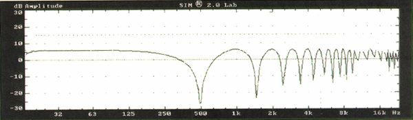
Figure 3: Effects of 1 ms delay on signal.
Equalizable room/speaker interaction is a minimum phase, second-order phenomenon exhibiting constant bandwidth and linear frequency spacing. Minimum phase frequency response anomalies occur when speakers are placed in proximity to boundaries such as walls, ceilings or soffitts. At best, 1/3-octave equalizers are constant-percentage bandwidth with logarithmic frequency spacing. Fig. 3 demonstrates the type of frequency response comb filtering caused by a 1ms echo, typical of a console reflection. Note that the combing is not logarithmically spaced (e.g. 1/3-octave) but rather a constant bandwidth of 1 kHz. The frequency center of the comb are an octave wide from 1 to 2 kHz and 1/10-octave wide from 10 to 20 kHz, meaning that a device with fixed 1/3-octave bandwidth can not create a complement. Combs rarely occur exactly at fixed ISO standard frequencies. Once again, parametrics offer the versatility to use a single filter to correct an overall trend in the response. With 1/3-octave EQ, several filters must interact to address this same issue.
Enlarge view
Figure 4: Effects of 1 ms delay on signal.
Enlarge view
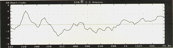
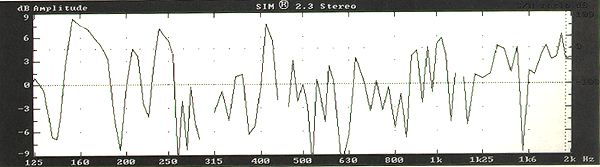
Figure 5: Midrange response viewed in 1/48-octave resolution (same as Fig. 4).
Part of the reason for using 1/3-octave equalizers for so long is due to the fact that until recently most analyzers were 1/3-octave. But 1/3-octave analysis does not offer enough resolution to actually see the whole story. Fig. 4 shows a 1/3-octave mid-band shot of a control room. Notice the hole from about 500 to 800 Hz. This would lead one to believe that some boost centered at 630 Hz on your 1/3-octave EQ would fix the problem. In actuality, viewing the 1/48-octave resolution in Fig. 5, we see that this is not a wide-band hole but a series of tight combs that should probably not be EQ'd. The 1/3-octave analyzer averaged this section out in a broad stroke. This is a simplfied picture, but it is accurate and is the rule rather than the exception. I strongly suggest that you look at your rooms with effective resolution is you really want to solve the problems.
There are now better solutions available to address room/speaker interactions than are currently in use. Without a huge investment, the quality of studio monitoring environments can be upgraded significantly, which is supposed to be one of the advantages to working in a "recording studio." If you don't agree, just make mine a double espresso with a twist please.